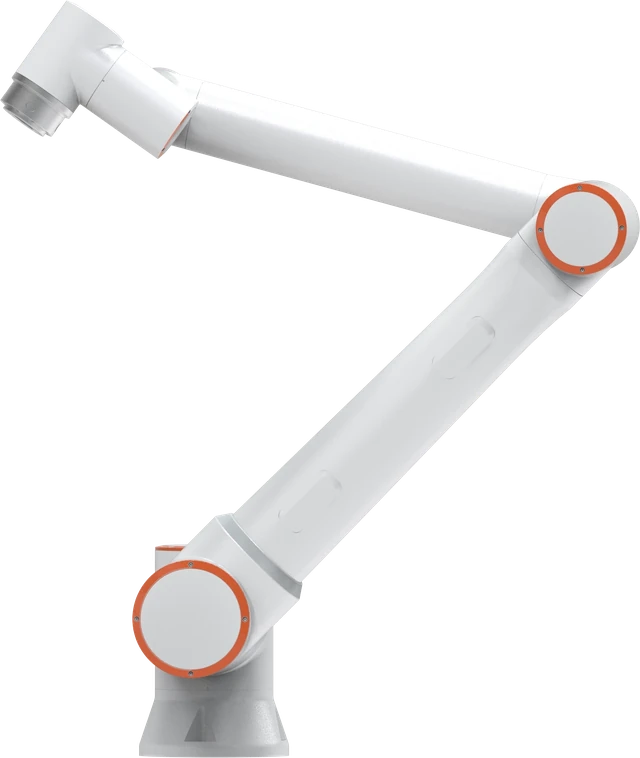
One configuration to evaluate for the requirements discussed here. Check tooling load, the complete motion path and process requirements before selecting the arm.
View FR10 specifications and quote considerationsPicture a laser-cut steel blank, 3 mm thick, full of slots, lying oiled on a stack. A suction cup lands on a slot and leaks. A jaw gripper cannot reach an edge until the sheet is lifted. A magnetic gripper needs only one accessible ferrous face, which earns it a place in sheet handling and press or CNC tending. The catch: catalogue force is measured on a thick, clean, flat test block. Below: which magnet type to ask for, how far rated force can fall, and what to test before a magnetic tool goes on a robot arm.
Magnet types and their power-loss behaviour
What the part does when the supply fails depends on magnet type.
| Type | How it switches | On loss of supply | What to check |
|---|---|---|---|
| Permanent magnet, pneumatically switched | Air moves the magnet between grip and release positions | Stays in its last state on designs described as bistable | Air pressure range, switching-state sensor |
| Electrically switched permanent or electro-permanent magnet | Electrical switching of the magnet system; no holding current | Holds, if the maker states it | Force steps, part detection, permitted switching rate |
| Electromagnet | Coil energised to hold | Releases | Whether a dropped part is acceptable |
Schmalz describes its SGM pneumatic magnetic grippers as permanent-magnet tools whose grip and deposit settings are maintained in the event of a power failure. OnRobot states that its electric MG10 magnetic gripper maintains its hold if power is lost or an emergency stop occurs. SCHUNK presents the EMH as an electro-permanent gripper with feedback on magnetization state and workpiece presence, and limits activations per minute because each one heats the unit. Goudsmit’s electro holding magnet page gives the contrast: its plain electromagnet releases immediately when the coil is switched off.
Holding through a power cut also means a part stays suspended until power returns, so write the recovery procedure into the cell’s risk assessment.
Why the rated holding force is not your holding force
Magswitch states on its AR110 product page that maximum breakaway was determined in a laboratory on 2 inch thick SAE 1018 steel with a 63 microinch surface finish, that the listed maximum forces are not safe lifting forces, and that it recommends a safe working load of 5:1 for most applications. The same page shows what thickness alone does on that model: 12,795 N on 50.8 mm plate, 9,797 N on 10 mm and 1,839 N on 3 mm. Those figures belong to one large unit and do not transfer to other magnets, but they show how thin material cuts the hold.
Goudsmit’s note on feasible forces of magnetic grippers lists the other reductions a buyer should expect:
- Material grade. Taking low-carbon steel as 100 percent, the note gives 85 percent for medium-carbon steel, 75 percent for high-carbon or alloyed steel, 45 percent for cast iron and 50 to 60 percent for ferritic and martensitic stainless. Austenitic stainless (AISI 304, 316), brass, aluminium and copper are listed as unsuitable.
- Air gap. Coatings, foils, rough surfaces, rust and dirt separate the poles from the steel and reduce the hold.
- Contact area. Perforations and partial coverage of the poles reduce force.
- Thickness. Thin sheet saturates, so the field cannot be fully used.
- Motion. Acceleration forces must stay well below the holding force, and sagging loads peel off the magnet.
Shear is a separate rating, because only friction resists sliding when the robot accelerates sideways. Goudsmit states for its electro holding magnets that maximum shear force is about a quarter of maximum holding force, and Magswitch lists 3,344 N maximum shear against 12,795 N breakaway for the AR110. Ask for the shear figure on your thickness.
Stacks, chips and residual magnetism
Single-sheet picking. A field strong enough to hold a thin sheet can reach through it and lift the next one. OnRobot gives ten force steps on the MG10 and cites separating thin sheets individually; Magswitch publishes a minimum de-stack thickness for the AR110. Treat double picks as a test item, and add detection if a double sheet would damage the press.
Chip pickup. In machine tending, a switched-on magnet collects swarf. Chips on the pole face become an air gap on the next pick and can mark a finished surface, so plan a blow-off or wipe step.
Residual magnetism. Steel parts can retain some magnetism after release. None of the product pages we read quantify it, so we give no figure. If a later step is sensitive to it, ask the vendor for data on your material and check it in the trial.
Magnet, vacuum or jaws for a steel part
Choose a magnet when the part is ferromagnetic, fairly flat at the pick face, and too perforated, oily or dusty for a cup. Choose vacuum when the surface seals well or the material is non-magnetic. Choose jaws when the part must be located accurately in the tool or pushed into a chuck; the finger-design guide covers that route. A magnet holds a part without centring it, so precise placement may need a nest or vision check. The end effector overview compares the wider tool families.
Sizing the FAIRINO arm around a magnetic tool
The gripper, its bracket and the part all count against payload. As an illustrative sum, a 0.8 kg magnetic gripper (the MG10’s published weight) plus a 0.5 kg bracket and a 3 kg blank is 4.3 kg, under the FAIRINO FR5’s 5 kg catalog payload but with little margin. Large sheets usually need several magnets on a frame to stop sagging, which moves the job to the FR10 (10 kg, 1,400 mm) or the FR20 (20 kg, 1,854 mm) for reach across a pallet or press bed. Catalog payload and reach only form a shortlist; check the frame’s centre of gravity against the model’s load diagram. For machine tending of plate beyond those figures, a larger industrial robot is the more suitable choice.
Trial checklist
- Test production parts in the thinnest gauge, highest-alloy grade and worst surface you run.
- Measure pull-off and sliding force and apply the vendor’s safety factor.
- Run the real path at programmed acceleration, including a stop while loaded.
- Cut air and power with a part held and record the result.
- Pick from a full stack down to the last sheet and count double picks.
- Confirm the robot program reads part-present and switching-state signals.
- Check release time, placed position and residual attraction.
- Run enough cycles to see chip build-up and heating.
If results are marginal, change the magnet count or the grip method before changing the robot. To review a ferrous-part application and suitable tooling, request a consultation with part material, thickness and surface condition.
Sources and further reading
Plan your next automation project
Share your parts, process, and production goals. Get help comparing robot options, planning the complete application, and deciding what to do next.
Request a consultation