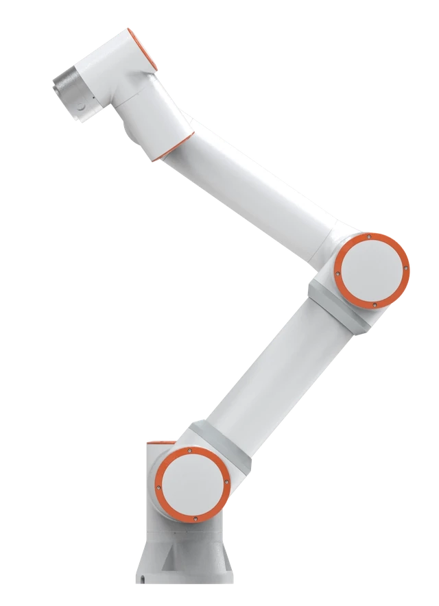
One configuration to evaluate for the requirements discussed here. Check tooling load, the complete motion path and process requirements before selecting the arm.
View FR5 specifications and quote considerationsEnd effectors are chosen from the part and the process backwards. How the part may be touched and what the process must do to it pick the tool family. The tool then sets the mass the arm carries, how far that mass sits from the flange, and which utilities must reach the wrist. For a robot cell, that puts tooling ahead of the model number. A FAIRINO FR5 and a FAIRINO FR10 can both move a 2 kg part until the gripper, fingers, adapter and cables are added to the load.
A task-to-tool map
Use the table to find the family, then follow the linked guides for detail.
| Task and part | Tool family to evaluate first | What it needs from the cell | Typical reason it fails a trial |
|---|---|---|---|
| Prismatic or blocky parts with two parallel faces | Parallel two-jaw gripper | Custom fingers, open and closed confirmation | Finger clearance at the fixture or chuck |
| Round billets, shafts and rings that must be centred | Three-jaw centric gripper | Stroke for the diameter range, chip protection | Jaw travel too short for the part family |
| Parts needing a wide jaw opening | Angular gripper | Swing clearance around the jaws | Grip point shifts with part size |
| Cartons, bags, panels and sealed flat surfaces | Vacuum cups or a foam vacuum pad | Vacuum generation, level sensing, blow-off | Leakage through porous or uneven surfaces |
| Ferrous sheet, blanks and perforated steel | Magnetic gripper | Switching air or 24 V, part detection | Thin sheet, coatings and shear loads reduce the hold |
| Fragile, irregular or food items | Soft or adaptive gripper | Cleanable contact material, modest speed | Low payload and loose position repeatability |
| Welding, screwdriving, dispensing, sanding | Process tool | Process supply, a calibrated tool point | Cable drag and an unverified tool point |
The range is wide even inside one catalogue. OnRobot’s product range lists finger, vacuum, magnetic and soft grippers, a screwdriver and a sander for the same class of arm. It publishes weights of 1.1 kg and 1.5 kg for two of its parallel grippers. These are one vendor’s figures, not a FAIRINO compatibility statement.
The deeper questions have their own guides: electric versus pneumatic actuation, finger design for parallel grippers, suction cup selection and magnetic grippers for ferrous parts.
Mass and centre of gravity come off the payload first
Rated payload covers everything beyond the flange: adapter plate, changer, gripper body, fingers, valves, sensors, carried cable and hose, and the part. As an illustrative sum, a 1.1 kg gripper with 0.4 kg of fingers and adapter leaves 3.5 kg of the FR5’s 5 kg catalog payload before accounting for other carried hardware and the applicable load limits. Long fingers, a dual gripper or an offset torch also move the combined centre of gravity away from the flange, so ask for the model’s load diagram with the proposal and check the offset as well as the mass.
The controller needs the same numbers. The FAIRINO web manual’s payload and tool-coordinate section (version 3.9.0) states that the end load’s weight and centre-of-mass coordinates must be set correctly, that the load mass cannot exceed the robot’s maximum load range, and that the tool coordinate system must be calibrated after a tool is installed. Our TCP calibration guide covers the tool-point record.
Utilities decide how clean the installation is
List what each candidate tool consumes: compressed air, vacuum, 24 V power, digital signals, a serial or fieldbus link, welding current, wire, gas, adhesive or abrasive. Then ask how each gets from the base to the wrist, because external hoses and cables add carried mass and limit wrist rotation. The FAIRINO manual refers to end-plate digital and analog outputs; confirm the channel count, connector and current limit for your model and controller version before choosing a gripper that depends on them.
If the cell needs more than one tool, a changer has to pass every utility through its interface, which the tool changer guide works through.
Check the flange drawing, not the standard’s name
Tool adapters are often specified by an ISO 9409-1 pattern. According to BSI’s record for BS EN ISO 9409-1:2004, the standard defines the main dimensions, designation and marking of a circular plate used as a mechanical interface, to support exchangeability and orientation of end effectors. The same scope statement says it does not correlate the interface with load-carrying ranges, so a matching bolt circle says nothing about whether the arm can carry the tool.
This guide does not quote a flange designation for any FAIRINO model, because the drawing for your configuration is the reliable reference. Request the dimensioned flange drawing for the exact model and suffix and compare bolt circle, thread, locating pin and centring diameter with the tool vendor’s adapter drawing.
How the tool changes the FAIRINO shortlist
- Light gripper, small part, short reach: start with the FR5 at 5 kg and 922 mm.
- Dual gripper for machine tending: two grippers, two finger sets and a bracket add mass and offset. The FR10 at 10 kg and 1,400 mm is the next model to check for machine tending.
- Heavy part close in: the FR16 carries 16 kg with a shorter 1,034 mm reach than the FR10, so check the layout before choosing it on payload alone.
- Large vacuum frame for cartons: frame mass and carton offset favour the FR20 at 20 kg and 1,854 mm in palletizing layouts.
- Welding torch: consider the welding configurations, such as the FR5-WML at 5 kg and 1,900 mm, sized for torch load and seam reach.
These catalog payload and reach values form a shortlist and do not validate a cell. Keep any of these example arms on the shortlist only when the complete load case fits with suitable margin. If the tool and part exceed the largest model’s load diagram, a conventional industrial robot is the better conversation.
The tool is part of the risk assessment
The OSHA Technical Manual chapter on industrial robot systems names parts release, gripper mechanism failure and end-effector power tool failure among struck-by hazards, and lists rounded corners and edges on the end effector and fixture among passive risk reduction measures for collaborative applications. A collaborative arm does not remove those hazards. Ask what each tool does on loss of air or power.
What to send before a tooling discussion
- Part samples or drawings with mass, material and permitted contact surfaces.
- Pick and place poses with clearances.
- Utilities at the cell: air, 24 V capacity, network.
- Confirmation signals the process needs.
- Number of part variants and how often the tool must change.
Discuss your automation project with that list and the follow-up can narrow the tool family and the arm together.
Sources and further reading
- OnRobot: end-of-arm tooling product range
- FAIRINO documentation: collaborative robot manual 3.9.0, base settings (TCP and end payload)
- BSI Knowledge: BS EN ISO 9409-1:2004, mechanical interfaces, plates
- OSHA Technical Manual, Section IV, Chapter 4: Industrial Robot Systems and Industrial Robot System Safety
Plan your next automation project
Share your parts, process, and production goals. Get help comparing robot options, planning the complete application, and deciding what to do next.
Request a consultation